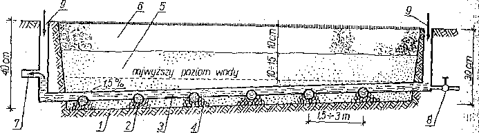
 Diagram of the "Cell System" installation for regulating the moisture level of the lawn: 1 - foil separating the installation from the ground, 2 - perforated plastic pipes ø 75 mm. stacked horizontally,-3 - main longitudinal cord (collecting and powering) stacked with a slope, 4 - gravel surrounding the cross tube, 5 – sand containing 10–30 % non-capillary spaces, 6 - a layer of sand mixed with peat in the ratio 1 : 1, 7 - overflow pipe that allows excess water to flow after exceeding the permissible level, 8 - water supply line valve, 9 - an air inlet.
Interesting technical solutions should therefore include a bidirectional installation designed by one of the Canadian companies specializing in setting up lawns. This solution has been used for several years under the name "CELL SYSTEM". The diagram of the construction of such an installation is shown in the figure. The most important features of this solution are:
— separation of the entire controlled substrate from the rest of the soil with polyethylene foil;
— the use of special connectors of the filter line with the power cord;
- introduction of airing holes for the entire system as the water recedes.
Operation of the depicted device is as follows. Excess rainwater, after exceeding the designed free water level, immediately flows down the network of pipes of the drainage conduit. Free water remaining in the 10-15 cm layer of sand in the summer is a reserve for the period 4-6 weeks.
This water penetrates into the roots with a network of sand capillaries. This sand contains 10-30% of non-capillary vessels, which ensure air retention. Such a percentage of non-capillary vessels is obtained by adding to grained sand 0,1-1 mm approx 30% fine gravel ∅ 3-5 mm.
When the water supply is exhausted, which can be signaled by installing a strain gauge in the substrate, it is supplemented to the required level from the water pipe connected to the installation.
Installation is as follows. An average depth of 35 trench is made–40 cm, with a decrease of approx 1,5%. After smoothing, the bottom of this trench is covered with a polyethylene film. Transverse pipes are placed on the foil (filters), then the longitudinal pipe, which is placed higher by half the thickness of the cross tubes. Special couplings are used to ensure this position of the pipes. Should be added, that the cross tubes are perforated on one side only and that side are laid down. After laying these pipes, they are covered with gravel to prevent floating parts from getting into the holes. Then the sand is poured to the designed lawn level. A layer of approx 5 cm of peat and mixed with sand to a depth 10 cm. Before mixing the peat, it is necessary to add mineral fertilizers, like for example. Azofoska in quantity 20-25 g / m² or another mixture with a similar composition. In such a prepared substrate, you can sow grass seeds or lay turf.